4N35 Optocoupler IC:
The 4N35 is a popular optocoupler device that includes an infrared LED and a phototransistor within a single package. Optocouplers are essential components for providing electrical isolation between input and output circuits. Let's explore the details of the 4N35 Optocoupler IC:
Datasheet:
- To access comprehensive technical information such as electrical characteristics, recommended operating conditions, and application notes, you can refer to the datasheet provided by the manufacturer. Datasheets are available on manufacturer websites or electronic component distributors.
Pinout:
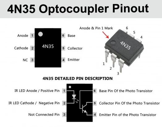
The 4N35 typically features 6 pins in a standard DIP (Dual Inline Package) configuration:
- Anode (A): Anode of the infrared LED.
- Cathode (K): Cathode of the infrared LED.
- Collector (C): Collector of the phototransistor.
- Emitter (E): Emitter of the phototransistor.
- No Connection (NC): Often a not connected pin.
- Base (B): Base of the phototransistor.
Circuit Diagram:
A simplified circuit diagram using a 4N35 Optocoupler can be depicted as follows:
NOTE: The resistor is often added for current limiting purposes to protect the LED.
Uses of 4N35 Optocoupler IC:
- Isolation: Acts as an isolation barrier between high and low voltage circuits, preventing interference and providing safety.
- Signal Transmission: Enables the transmission of signals across isolated circuits without direct electrical connection.
- Voltage Level Shifting: Helps in shifting voltage levels between different parts of a system.
- Switching Circuits: Utilized in switching circuits to control high-power devices with low-power signals.
- Feedback Systems: Used in feedback systems to transmit feedback signals while maintaining electrical isolation.
- Motor Controls: Applied in motor control systems to ensure isolation and safety.
- Logic Signal Isolation: Enables isolation of logic level signals in digital systems.
- Feedback Control Systems: Employed in feedback control systems such as power supply feedback circuits.
Conclusion:
The 4N35 Optocoupler IC is a versatile component used for various applications requiring electrical isolation and signal transmission across isolated circuits. By understanding the pinout, circuit diagrams, and applications of the 4N35, you can effectively integrate it into your electronic designs to ensure safe and reliable operation in diverse scenarios.